Wednesday, August 31, 2016

Cisco Meeting Server (CMS) Part 1 - Making your first call to CMS

Part 1 - Making your first call to CMS
Part 2 - XMPP and CMA
Part 3 - Integrating Core and Edge

Cisco has rebranded the Acano solution to Cisco Meeting Server (CMS), and this post is target to help you to set basic things up and make your first call to a CMS Space and CMS IVR.

1. First of all, deploy your CMS ova with vCenter.
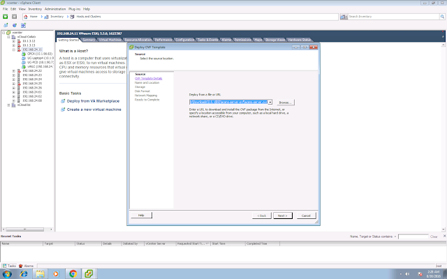
 

2.  It will spend around 10-15 minutes for the first time boot up.
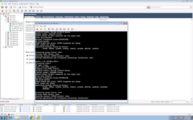


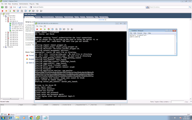
3.  Login via CLI.  Default credential is admin/admin.  You are required to change your CMS admin password for the first time login.


4. You can check your interface configuration with the command "ipv4 a".  By default DHCP is enabled.
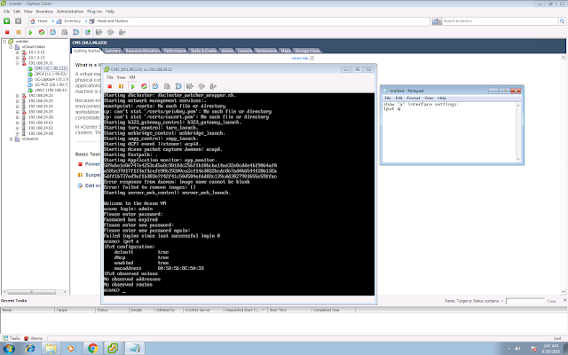


Set your static IP address with the command "ipv4 a add 10.1.90.123/24 10.1.90.254", in my case 10.1.90.123 is the IP address of my CMS, 10.1.90.254 is the default gateway.
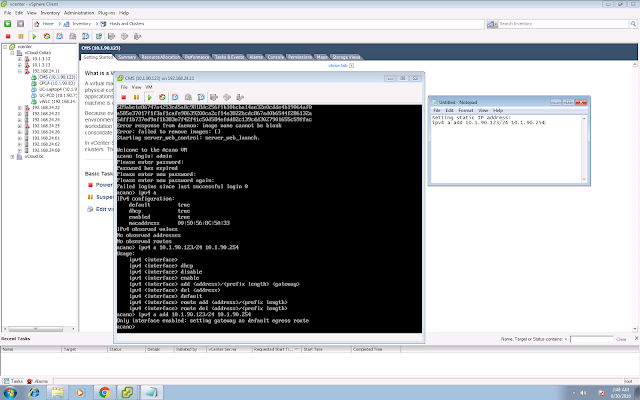


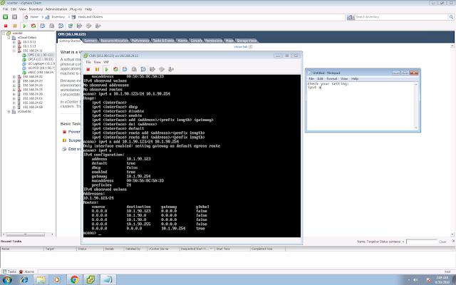
Check your interface configuration again with the command "ipv4 a".


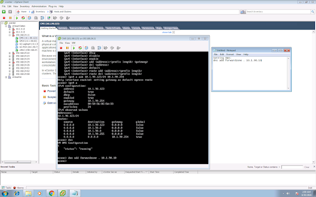
5.  You can config your DNS server settings with the command "dns add forwardzone . 10.1.90.10", which will forward all the DNS query (. means all domain) to my DNS server 10.1.90.10.


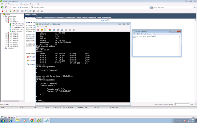
Check your DNS configuration with the command "dns".


6. Create self-signed cert for HTTPS web admin with the command "pki selfsigned webadmin".  In this case webadmin will be the filename of your self-signed cert.
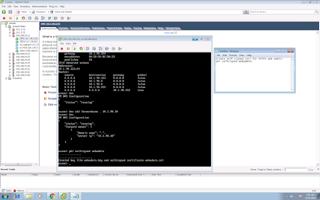


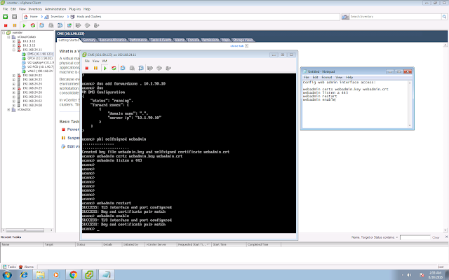
7. Config web admin interface access.

webadmin certs webadmin.key webadmin.crt
webadmin listen a 443
webadmin restart
webadmin enable


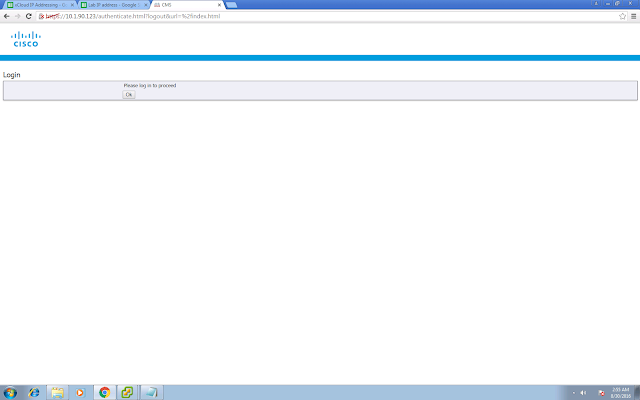
Try to access your web admin page:


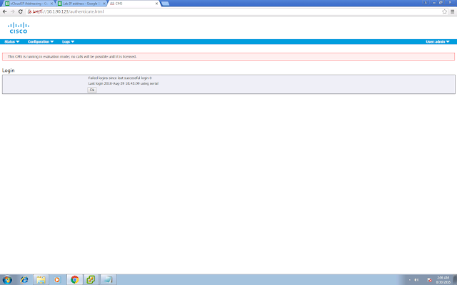
Login with your admin credential:



You will see there is a warning saying that CMS is running in evaluation mode as no license is installed.


8. If you are going to enable WebBridge (accessible by the WebRTC client), we have to change the web admin listening port from 443/tcp to something else, say for example 445/tcp.

webadmin disable
webadmin listen a 445
webadmin enable
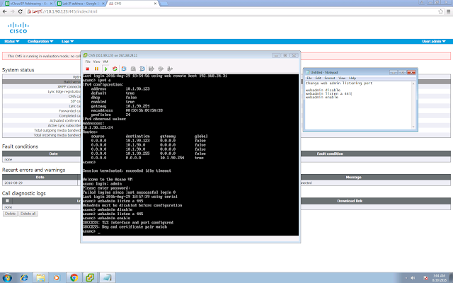


9. Copy the license file to CMS via sFTP or SCP.  In my case I used my mac built in sftp client and upload the file to CMS.

sftp admin@10.1.90.123
put cms.lic

10. Enable and config CallBridge, which is the core components for all the audio and video call terminations.

pki selfsigned callbridge
callbridge certs callbridge.key callbridge.crt
callbridge listen a
callbridge restart
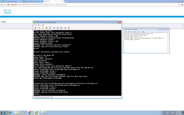


11. Login the admin page again, you should seen something similar to mine below.


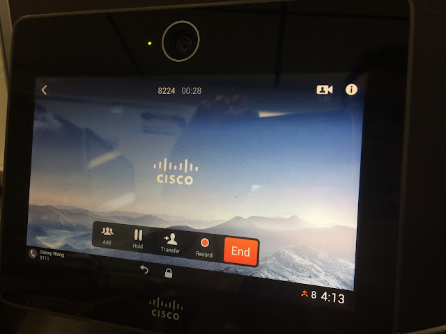
12. Enable IVR, in my case my IVR number is 8224, so when you make a call to 8224, you will see the default Cisco background and listen to the default IVR prompt.  The IVR number can be configured in Configuration > General > IVR Numeric ID.
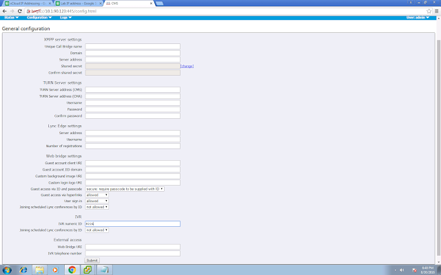


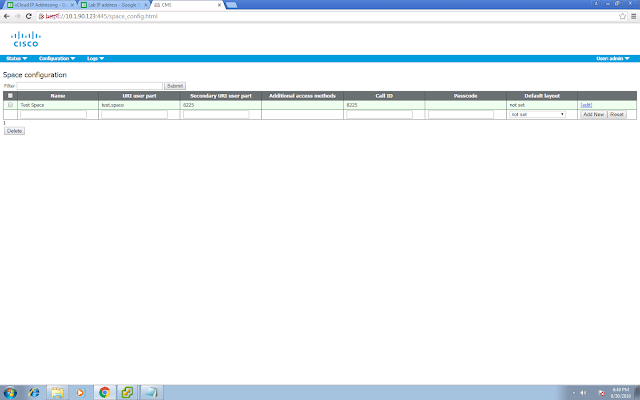
13. You can also create your Space to call in, so that you don't need to key in any Call ID by calling the IVR, by directly calling to the Space.


14.  You will need to create your SIP trunk on UCM, pointing to CMS.  In my case it is a lab environment and I am using a non-secure setting so I don't need to deal with the certs.

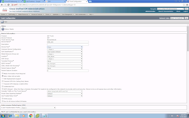


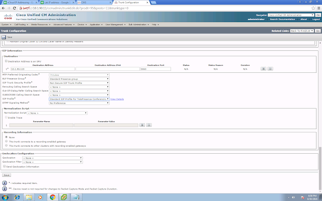
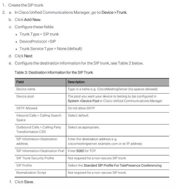
The destination address is your CMS address.  You will need to choose the Telepresence Conferencing SIP Profile.  No Normalization Script is required.

Extracted from the guide:

15. Config your route pattern.  In my case my pattern is 822[45].
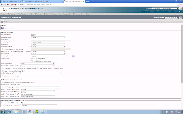


Try to place your test call.  You should now able to call your IVR number (8224 in my case) and Space number (8225 in my case) from your UCM-registered devices.


Part 1 - Making your first call to CMS
Part 2 - XMPP and CMA
Part 3 - Integrating Core and Edge

Friday, July 29, 2016

Using Scratch to control Raspberry Pi GPIO

In the previous post, I have built my first circuit and able to control the LED light using the gpio command:
http://pandaeatsbamboo.blogspot.hk/2016/07/the-hello-world-circuit-with-raspberry.html

Similar control can be done via Scratch, this is the official tutorial:
https://www.raspberrypi.org/blog/a-new-version-of-scratch-for-raspberry-pi-now-with-added-gpio/

This is a super simple Scratch script to illustrate this:


In this simple script, when you click the flag icon, it will set the gpio pin 17 (BCM) to 1 to switch on the LED.  When you press the spacebar on your keyboard, it will set the gpio pin 17 to 0 to switch off the LED.  With this you can incorporate the GPIO control into your own scratch script.  Give it a try!

Tuesday, July 26, 2016

The "Hello World" circuit with Raspberry - Single LED

Probably the "Hello World" of building a simple circuit with Raspberry is a single LED circuit.  So I decided to give it a try.  Not difficult frankly speaking, just to get all the ingredients together and there are plenty of goods tutorial if you spend a minute to google.

This is the official URL that you can first check it out:
https://www.raspberrypi.org/documentation/usage/gpio-plus-and-raspi2/

The circuit that I've used is exactly the same as the one you can find from the above URL, except that the "switch" is not a physical one, I used the gpio command to control it.


This is how it looks physically.  I've connected the GPIO pin to my breadboard using the female-to-male jumper cable.  Physical pin 11 is used for +ve and physical pin 6 is the ground pin.


Check out this link about breadboard.  An other things about building a circuit.


Some holes (usually the top and bottom rows) are connected in row and some (usually the middle) are in column.  

I've followed this link and used a 330 ohm resistor.  Check your LED spec to decide the correct resistor.  My LED works fine in a 11mA current circuit so 330 ohm resistor is good for my case.

Also check out the above link for LED.  The LED should have 2 legs, the longer leg is +ve and shorter leg is -ve.

One thing that I've spent quite some time is the pinout.  The BCM and physical board pin numbering is a bit confusing.  Say for my case, I've used physical pin 11, and in BCM numbering it is pin 17.  It will spend you hours to troubleshoot if you don't get it right.

You can use the gpio readall command to print out all its number convention and other details.


Another thing is, your physical GPIO pin 11 will be providing 3.3V power and you have to change its mode to OUT.  You can do it with the gpio command below:


gpio -1 means you are referring to the physical pinout numbering.

gpio -g means you are referring to the BCM pinout numbering.


This is a python script to switch on then off the LED light instead of using the gpio command.  You can find a similar script from the link provided above.  The only difference here is I am using GPIO.BOARD which means I'm referring to the physical pin number 11.


If you want to use the BCM numbering, then you can setmode to GPIO.BCM

Hope it will save you some time from troubleshooting layer 1 problem and to build up your first circuit with Raspberry!


Thursday, July 14, 2016

Raspberry Pi Cam + Cisco Spark - Motion Detection Demo

In the previous post, I've setup a Raspberry Pi Surveillance camera with Live streaming capability, and it can also save a video file when motion is detected.

http://pandaeatsbamboo.blogspot.com/2016/07/live-streaming-video-from-raspberry-pi.html

Spark integration is done too so that when motion is detected, a Spark message is posted with video files.  This is how it works:


Live streaming video from the Raspberry Pi with Camera v2

Just got my Raspberry Pi Camera v2, cannot wait to unbox and play with it.


I didn't get a good case to fit in the camera module, but it works.  :)


First of all you can start by taking a picture to make sure your camera is working fine:

raspistill -o image.jpg

To capture your first video, you can use the command raspivid:

raspivid -o video.h264

The video is in raw h.264 format.  It is fine to be played back by my omxplayer on the Raspberry, however if you want most of the other video players to play it, it will be better to convert the file into mp4.

sudo apt-get install gpac
MP4Box -fps 30 -add video.h264 video.mp4

For some application such as "motion", the motion detection and video streaming applications, it needs to recognised the video device as /dev/video0.  It is not the case by default for the Pi Camera.

To enable that, you need to run:

sudo modprobe bcm2835-v4l2

You can also put this command in /etc/rc.local so that the next reboot it will run automatically.

Motion is an open source motion detection and surveillance software which can help you to convert your Raspberry Pi into a home surveillance camera.  To start with, you can get the motion package:

sudo apt-get install motion

A few parameters under motion.conf that you can change, such as:

daemon on

which makes the motion run in background when you start the motion server.

You can also change the resolution in the conf file:
width 1280
height 720

change the following parameter to off so that you can access from host other than localhost:
stream_localhost off
webcontrol_localhost off

You can now access the stream via http::8081


And you will get a bunch of files in your home directory, make sure you have enough storage, if not probably you might need to do it off box to a NAS or whatever it is.  These files are created when motion is detected.


These are the links that I've used to aid my setup, listing all here for your reference:
http://www.instructables.com/id/Raspberry-Pi-as-low-cost-HD-surveillance-camera/?ALLSTEPS
http://www.makeuseof.com/tag/raspberry-pi-camera-module/
http://www.raspberrypi-spy.co.uk/2013/05/capturing-hd-video-with-the-pi-camera-module/

Wednesday, July 13, 2016

Expressway 8.8 registration - in action

In the previous post I've shared that the latest Expressway 8.8 supports endpoint registration:
http://pandaeatsbamboo.blogspot.com/2016/07/expressway-88-video-endpoint.html

I want to give it a try therefore I have upgraded my lab Expressway C to the latest version 8.8.  First of all there is a getting started wizard, and it will let you decide what role the Expressway will play and it will customize the UI accordingly and hide those that are not needed.


New license types are introduced (Room systems, Desktop systems), and it aligns with the UCM licensing model.  You will need UCL Enhanced / CUWL for desktop systems, and Telepresence room system license for Room systems.


I've some difficulties in using the endpoint activation wizard to register it to Expressway.  However it works well when I manually do it on the codec web admin page.  Under SIP configuration:


It is now registered, it can be seen from the codec admin page:


From the Expressway admin page:

This is how it looks on the DX70 itself:


Sunday, July 10, 2016

Using Web and Cisco Spark to control a Lego EV3 Robot


I have bought the Lego Mindstorms EV3 robot for more than 2 years, however I didn't spend any time on it until recently.  My daughter was sick and she has to stay at home, to keep her busy I built the EV3 together with her and we had run some pre-set missions to make the robot move and did some simple tasks.  It works great, except that I have to use the Mindstorm software to program it.


There is also another iPhone app to give you basic control of your robot, however it only accepts bluetooth connection, which makes me a lot less flexible compare with Wifi.


I have done some googling and find this post:
http://programmablebrick.blogspot.hk/2014/11/seanbot-ev3-robot-controlled-via-web.html

It looks interesting to me and I would want to make it my first EV3 project.  This is what I've done:

1. Get an microSD card.  So happen I've found one old 2GB card at home and I've used that for this project.  Flash it with the ev3dev OS following the instruction in this page, it is based on Debian Linux:
http://www.ev3dev.org/docs/getting-started/

2. Putting the microSD card into my EV3 and power it on.  It will not affect your original firmware in EV3, it is just like dual booting another OS.


3. Setting up the wireless network.  I've bought a wireless USB dongle from a local computer store, and it is less than US$9.  It works like a charm.  I did purposely pick one without 802.11ac, older model, claim to have Linux support.  Just bet on it, provided that it is so cheap.


4. Plug that into the USB port of EV3.  Use the screen on EV3 to choose my home wifi network, and entered the WPA PSK.  It is now connected, and able to access the Internet.


5. SSH to the box.  Use apt-get to get the packages, make sure you did a apt-get upgrade and update before you download the other packages.


sudo apt-get update; sudo apt-get upgrade
sudo apt-get install apache2 libapache2-mod-php5 unzip

6. Download the files in zip in this github project -  https://github.com/dwalton76/LegoEV3D4.  Unzip and copy these contents into your apache document root, in my case it is /var/www/html.  I download it to my Mac and then scp to the EV3, unzip it then copy it to the document root.

7. Install the python-ev3 on EV3 - https://github.com/topikachu/python-ev3.  My version of python is 2.7, therefore these are the commands that I've issued to my EV3.

Python 2.7

apt-get update
apt-get install virtualenv virtualenvwrapper python-setuptools python-smbus python-pil
source /etc/bash_completion.d/virtualenvwrapper
mkvirtualenv ev3_py27 --python=/usr/bin/python2.7 --system-site-packages
workon ev3_py27
easy_install -U python-ev3
type deactive to exit

8. Download the python-ev3 project in zip file - https://github.com/topikachu/python-ev3.  Similar to step 6, copy the content to the EV3.  In python-ev3, there is a ev3 folder.  Make sure this folder is copied to /var/www/html.  You will need to make sure you do this otherwise your LegoR2D2.py will not work.

9. Some python libraries dependencies need to be resolved, and this is what I've done:
easy_install web.py

10.  Start your apache using the command /etc/init.d/apache2 start.  Run the LegoR2D2 python scripts with sudo.  tcp/8080 will be listened after you run the script.


11. Launch your web browser.  I have tried Chrome and Firefox, for some reasons it only works on my Firefox, probably it is something specific to my laptop.  By the way this is what you will see:


12.  Click on the arrows to move your robot!  Is that it?  No!  How about we using a Cisco Spark Chatbot to control the EV3?