Showing posts with label IOS. Show all posts

Friday, March 7, 2014

IOS vs IOS XR - Enable Telnet Access to the router

In normal IOS if you want to enable telnet access, what you want to need is to configure under line vty and configure transport telnet:

line vty 0 4
 exec-timeout 0 0
 privilege level 15
 logging synchronous
 login authentication noauth
 transport input telnet ssh

In IOS XR you need to enable telnet server with the command telnet ipv4 server:

telnet ipv4 server max-servers 10

IOS vs IOS XR - Static Route

After working over a year on IOS XR, I've found that it is not as difficult as initial thought, you just need to get used to the syntax and the way it arranges the configuration.  It got less configuration directly under the interface, in some scenarios like you want to remove your configuration in lab practice, you will find it is more convenient to do so. (e.g. no mpls ldp, no rsvp, no mpls traffic-eng, compare with IOS you have to "no" all these configurations under interfaces)

In IOS when you are defining a static route, the command is:

ip route 0.0.0.0 0.0.0.0 10.1.40.30

However in IOS XR, you will be configured under the "router static" process, much neater and easier to read:

router static 
address-family ipv4 unicast
0.0.0.0/0 10.1.40.30

If you have vrf it looks like this

router static 
   address-family ipv4 unicast
   0.0.0.0/0 10.1.40.30
   vrf panda 
      address-family ipv4 unicast
      10.1.9.1/32 int gi0/0/0/2


Thursday, November 22, 2012

ISR G2 - cme-srst license

On ISRG2, in order to use cme-srst feature, just installing uck9 license is not good enough.  You also need to activate the cme-srst license by accepting the end user agreement.  After that you can use this feature for 12 years.

http://www.cisco.com/en/US/docs/routers/access/sw_activation/SA_on_ISR.html#wp1155517

Here is the command you need to issue:
config t
license accept end user agreement

reload your router then check:


SRST-R2#sh license det cme-srst
Feature: cme-srst                        Period left: 8  weeks 3  days
Index: 1        Feature: cme-srst                          Version: 1.0
        License Type: EvalRightToUse
        License State: Active, In Use
            Evaluation total period: 8  weeks 4  days
            Evaluation period left: 8  weeks 3  days
            Period used: 38 minutes 3  seconds
            Transition date: Jan 21 2013 17:12:02
        License Count: 20/0  (In-use/Violation)
        License Priority: Low
        Store Index: 7
        Store Name: Built-In License Storage

Be careful that before you do this step, you can still issue the CME-SRST command, it just doesn't work!  The phone cannot be registered with the reject message

Nov 22 09:08:32.987: %IPPHONE-6-REG_ALARM: 24: Name=SEP588D09357799 Load=SCCP6945.9-3-1-3 Last=Phone-Reg-Rej

My IOS version:  15.2(4)M2


Friday, April 13, 2012

Easy Virtual Network

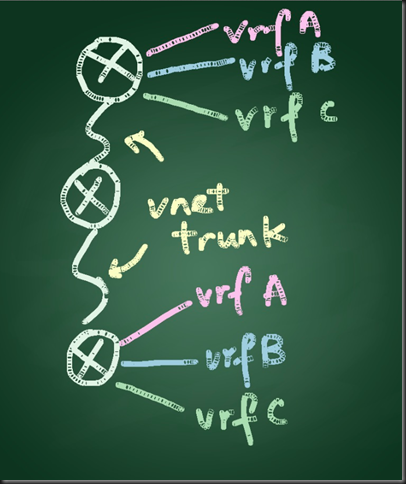
Scenario: In this scenario there are 3 routers interconnected, with 3 VRFs namely Android, IOS and WP7 created.  VNET trunk is configured in order to reduce the complexity and administration effort in configuring the routers in between.

Reference:  http://www.cisco.com/en/US/docs/ios/ios_xe/evn/configuration/guide/evn_confg_xe.html#wp1060221

Topology

VRF android (eth1/0), iOS (eth1/1) and wp7 (eth1/2) -- R4 (eth1/3 vnet trunk) -- (eth1/3 vnet trunk) R5 (eth1/0 vnet trunk) -- (eth1/3 vnet trunk) R6 -- VRF android (eth1/0), iOS (eth1/1) and wp7 (eth1/2)  
Image(14)

R4 Config

Current configuration : 2285 bytes

!

! Last configuration change at 01:38:17 HKT Sat Mar 24 2012

!

version 15.2

service timestamps debug datetime msec

service timestamps log datetime msec

!

hostname R4

!

boot-start-marker

boot-end-marker

!

!

vrf definition android

vnet tag 1001

!

address-family ipv4

exit-address-family

!

vrf definition ios

vnet tag 1002

!      

address-family ipv4

exit-address-family

!

vrf definition wp7

vnet tag 1003

!

address-family ipv4

exit-address-family

!

!

no aaa new-model

!

!

!

clock timezone HKT 8 0

ip cef

!

!

!

!

!

!

no ipv6 cef

!

!

multilink bundle-name authenticated

!

!

!

!

!

!

!

!

!

!

!

!

!

interface Ethernet0/0

no ip address

shutdown

!

interface Ethernet0/1

no ip address

shutdown

!

interface Ethernet0/2

no ip address

shutdown

!

interface Ethernet0/3

no ip address

shutdown

!

interface Ethernet1/0

 vrf forwarding android

ip address 10.1.1.1 255.255.255.0

!

interface Ethernet1/1

 vrf forwarding ios

ip address 10.2.2.1 255.255.255.0

!

interface Ethernet1/2

 vrf forwarding wp7

ip address 10.3.3.1 255.255.255.0

!

interface Ethernet1/3

 vnet trunk

ip address 192.168.1.1 255.255.255.0

 ip ospf vnet area 0

vnet name android

  ip ospf 2 area 0

!

vnet name ios

  ip ospf 3 area 0

!

vnet name wp7

  ip ospf 4 area 0

!

!

interface Serial2/0

no ip address

shutdown

serial restart-delay 0

!

interface Serial2/1

no ip address

shutdown

serial restart-delay 0

!

interface Serial2/2

no ip address

shutdown

serial restart-delay 0

!

interface Serial2/3

no ip address

shutdown

serial restart-delay 0

!

interface Serial3/0

no ip address

shutdown

serial restart-delay 0

!

interface Serial3/1

no ip address

shutdown

serial restart-delay 0

!

interface Serial3/2

no ip address

shutdown

serial restart-delay 0

!

interface Serial3/3

no ip address

shutdown

serial restart-delay 0

!

router ospf 2 vrf android

router-id 1.1.1.2

network 0.0.0.0 255.255.255.255 area 0

!

router ospf 3 vrf ios

router-id 1.1.1.3

network 0.0.0.0 255.255.255.255 area 0

!

router ospf 4 vrf wp7

router-id 1.1.1.4

network 0.0.0.0 255.255.255.255 area 0

!

router ospf 1

router-id 1.1.1.1

network 0.0.0.0 255.255.255.255 area 0

!

ip forward-protocol nd

!

!

no ip http server

!

!

!

!

control-plane

!

!

line con 0

logging synchronous

line aux 0

line vty 0 4

login

!

!

end

R5 Config

Building configuration...

Current configuration : 2290 bytes

!

version 15.2

service timestamps debug datetime msec

service timestamps log datetime msec

!

hostname R5

!

boot-start-marker

boot-end-marker

!

!

vrf definition android

vnet tag 1001

!

address-family ipv4

exit-address-family

!

vrf definition ios

vnet tag 1002

!

address-family ipv4

exit-address-family

!

vrf definition wp7

vnet tag 1003

!

address-family ipv4

exit-address-family

!

!

no aaa new-model

!

!

!

clock timezone HKT 8 0

ip cef

!

!

!

!

!

!

no ipv6 cef

!

!        

multilink bundle-name authenticated

!

!

!

!

!

!

!

!

!

!

!

!

!

interface Ethernet0/0

no ip address

shutdown

!

interface Ethernet0/1

no ip address

shutdown

!

interface Ethernet0/2

no ip address

shutdown

!

interface Ethernet0/3

no ip address

shutdown

!

interface Ethernet1/0

 vnet trunk

ip address 192.168.2.1 255.255.255.0

ip ospf vnet area 0

vnet name android

  ip ospf 2 area 0

!

vnet name ios

  ip ospf 3 area 0

!

vnet name wp7

  ip ospf 4 area 0

!

!

interface Ethernet1/1

no ip address

shutdown

!

interface Ethernet1/2

no ip address

shutdown

!

interface Ethernet1/3

vnet trunk

ip address 192.168.1.2 255.255.255.0

 ip ospf vnet area 0

vnet name android

  ip ospf 2 area 0

!

vnet name ios

  ip ospf 3 area 0

!

vnet name wp7

  ip ospf 4 area 0

!

!

interface Serial2/0

no ip address

shutdown

serial restart-delay 0

!

interface Serial2/1

no ip address

shutdown

serial restart-delay 0

!

interface Serial2/2

no ip address

shutdown

serial restart-delay 0

!

interface Serial2/3

no ip address

shutdown

serial restart-delay 0

!

interface Serial3/0

no ip address

shutdown

serial restart-delay 0

!

interface Serial3/1

no ip address

shutdown

serial restart-delay 0

!

interface Serial3/2

no ip address

shutdown

serial restart-delay 0

!

interface Serial3/3

no ip address

shutdown

serial restart-delay 0

!

router ospf 2 vrf android

router-id 2.2.2.2

network 0.0.0.0 255.255.255.255 area 0

!

router ospf 3 vrf ios

router-id 2.2.2.3

network 0.0.0.0 255.255.255.255 area 0

!

router ospf 4 vrf wp7

router-id 2.2.2.4

network 0.0.0.0 255.255.255.255 area 0

!

router ospf 1

router-id 2.2.2.1

network 0.0.0.0 255.255.255.255 area 0

!

ip forward-protocol nd

!

!

no ip http server

!

!

!

!

control-plane

!

!

line con 0

logging synchronous

line aux 0

line vty 0 4

login   

!

!

end

R6 Config

Building configuration...

Current configuration : 2285 bytes

!

! Last configuration change at 01:39:03 HKT Sat Mar 24 2012

!

version 15.2

service timestamps debug datetime msec

service timestamps log datetime msec

!

hostname R6

!

boot-start-marker

boot-end-marker

!

!

vrf definition android

vnet tag 1001

!

address-family ipv4

exit-address-family

!

vrf definition ios

vnet tag 1002

!      

address-family ipv4

exit-address-family

!

vrf definition wp7

vnet tag 1003

!

address-family ipv4

exit-address-family

!

!

no aaa new-model

!

!

!

clock timezone HKT 8 0

ip cef

!

!

!

!

!

!

no ipv6 cef

!

!

multilink bundle-name authenticated

!

!

!

!

!

!

!

!

!

!

!

!

!

interface Ethernet0/0

no ip address

shutdown

!

interface Ethernet0/1

no ip address

shutdown

!

interface Ethernet0/2

no ip address

shutdown

!

interface Ethernet0/3

no ip address

shutdown

!

interface Ethernet1/0

vrf forwarding android

ip address 10.4.4.1 255.255.255.0

!

interface Ethernet1/1

 vrf forwarding ios

ip address 10.5.5.1 255.255.255.0

!

interface Ethernet1/2

 vrf forwarding wp7

ip address 10.6.6.1 255.255.255.0

!

interface Ethernet1/3

 vnet trunk

ip address 192.168.2.2 255.255.255.0

ip ospf vnet area 0

vnet name android

  ip ospf 2 area 0

!

vnet name ios

  ip ospf 3 area 0

!

vnet name wp7

  ip ospf 4 area 0

!

!

interface Serial2/0

no ip address

shutdown

serial restart-delay 0

!

interface Serial2/1

no ip address

shutdown

serial restart-delay 0

!

interface Serial2/2

no ip address

shutdown

serial restart-delay 0

!

interface Serial2/3

no ip address

shutdown

serial restart-delay 0

!

interface Serial3/0

no ip address

shutdown

serial restart-delay 0

!

interface Serial3/1

no ip address

shutdown

serial restart-delay 0

!

interface Serial3/2

no ip address

shutdown

serial restart-delay 0

!

interface Serial3/3

no ip address

shutdown

serial restart-delay 0

!

router ospf 2 vrf android

router-id 3.3.3.2

network 0.0.0.0 255.255.255.255 area 0

!

router ospf 3 vrf ios

router-id 3.3.3.3

network 0.0.0.0 255.255.255.255 area 0

!

router ospf 4 vrf wp7

router-id 3.3.3.4

network 0.0.0.0 255.255.255.255 area 0

!

router ospf 1

router-id 3.3.3.1

network 0.0.0.0 255.255.255.255 area 0

!

ip forward-protocol nd

!

!

no ip http server

!

!

!

!

control-plane

!

!

line con 0

logging synchronous

line aux 0

line vty 0 4

login

!

!

end

Show command

R5#sh ip ospf nei

Neighbor ID     Pri   State           Dead Time   Address         Interface

1.1.1.1           1   FULL/DR         00:00:33    192.168.1.1     Ethernet1/3

3.3.3.1           1   FULL/BDR        00:00:37    192.168.2.2     Ethernet1/0

1.1.1.4           1   FULL/DR         00:00:36    192.168.1.1     Ethernet1/3.1003

3.3.3.4           1   FULL/BDR        00:00:31    192.168.2.2     Ethernet1/0.1003

1.1.1.3           1   FULL/DR         00:00:38    192.168.1.1     Ethernet1/3.1002

3.3.3.3           1   FULL/BDR        00:00:31    192.168.2.2     Ethernet1/0.1002

1.1.1.2           1   FULL/DR         00:00:32    192.168.1.1     Ethernet1/3.1001

3.3.3.2           1   FULL/BDR        00:00:30    192.168.2.2     Ethernet1/0.1001

R5#sh ip int brie

Interface              IP-Address      OK? Method Status                Protocol

Ethernet0/0            unassigned      YES NVRAM  administratively down down   

Ethernet0/1            unassigned      YES NVRAM  administratively down down   

Ethernet0/2            unassigned      YES NVRAM  administratively down down   

Ethernet0/3            unassigned      YES NVRAM  administratively down down   

Ethernet1/0            192.168.2.1     YES NVRAM  up                    up     

Ethernet1/0.1001       192.168.2.1     YES NVRAM  up                    up    

Ethernet1/0.1002       192.168.2.1     YES NVRAM  up                    up    

Ethernet1/0.1003       192.168.2.1     YES NVRAM  up                    up    

Ethernet1/1            unassigned      YES NVRAM  administratively down down   

Ethernet1/2            unassigned      YES NVRAM  administratively down down   

Ethernet1/3            192.168.1.2     YES NVRAM  up                    up     

Ethernet1/3.1001       192.168.1.2     YES NVRAM  up                    up    

Ethernet1/3.1002       192.168.1.2     YES NVRAM  up                    up    

Ethernet1/3.1003       192.168.1.2     YES NVRAM  up                    up     

Serial2/0              unassigned      YES NVRAM  administratively down down   

Serial2/1              unassigned      YES NVRAM  administratively down down   

Serial2/2              unassigned      YES NVRAM  administratively down down   

Serial2/3              unassigned      YES NVRAM  administratively down down   

Serial3/0              unassigned      YES NVRAM  administratively down down   

Serial3/1              unassigned      YES NVRAM  administratively down down   

Serial3/2              unassigned      YES NVRAM  administratively down down   

Serial3/3              unassigned      YES NVRAM  administratively down down    

R5#sh ip route vrf android

Routing Table: android

Codes: L - local, C - connected, S - static, R - RIP, M - mobile, B - BGP

       D - EIGRP, EX - EIGRP external, O - OSPF, IA - OSPF inter area

       N1 - OSPF NSSA external type 1, N2 - OSPF NSSA external type 2

       E1 - OSPF external type 1, E2 - OSPF external type 2

       i - IS-IS, su - IS-IS summary, L1 - IS-IS level-1, L2 - IS-IS level-2

       ia - IS-IS inter area, * - candidate default, U - per-user static route

       o - ODR, P - periodic downloaded static route, H - NHRP, l - LISP

       + - replicated route, % - next hop override

Gateway of last resort is not set

      10.0.0.0/24 is subnetted, 2 subnets

O        10.1.1.0 [110/20] via 192.168.1.1, 00:08:53, Ethernet1/3.1001

O        10.4.4.0 [110/20] via 192.168.2.2, 00:08:24, Ethernet1/0.1001

      192.168.1.0/24 is variably subnetted, 2 subnets, 2 masks

C        192.168.1.0/24 is directly connected, Ethernet1/3.1001

L        192.168.1.2/32 is directly connected, Ethernet1/3.1001

      192.168.2.0/24 is variably subnetted, 2 subnets, 2 masks

C        192.168.2.0/24 is directly connected, Ethernet1/0.1001

L        192.168.2.1/32 is directly connected, Ethernet1/0.1001

R5#show derived-config int eth1/3.1001

Building configuration...

Derived configuration : 183 bytes

!

interface Ethernet1/3.1001

description Subinterface for VNET android

encapsulation dot1Q 1001

vrf forwarding android

ip address 192.168.1.2 255.255.255.0

ip ospf 2 area 0

end

Service Advertisement Framework (SAF) Testing

Scenario:  In this test lab setup, there are 2 CM clusters and 1 CME and they are using SAF to advertise and learn their dial plan.  Both CM clusters are sharing the same SAF Forwarder, on the other hand CME are co-host with the SAF Forwarder using the same ISRG2 router.

The IOS version is 15.2, and it is a bit different from the configuration in the past.  The “external label” is removed from the EIGRP service family configuration, the new XMCP service routing is introduced.  The SAF Forwarder is the XMCP server and the UCM is the XMCP client.

Topology:

Image(1)

SAF Forwarder Configuration (for both UCM clusters)

SAF1#sh run

Building configuration...
Current configuration : 1958 bytes
!
! Last configuration change at 19:18:45 HKT Fri Mar 23 2012
version 15.2
service timestamps debug datetime msec
service timestamps log datetime msec
no service password-encryption
!
hostname SAF1
!
boot-start-marker
boot-end-marker
!
!
enable password cisco
!
no aaa new-model
clock timezone HKT 8 0
mmi polling-interval 60
no mmi auto-configure
no mmi pvc
mmi snmp-timeout 180
!
!
!
!
!
ip cef
no ipv6 cef
multilink bundle-name authenticated
!
!
!
!
!
!
!
username cisco
!
!
!
!
!
!
interface Ethernet0/0
no ip address
shutdown
!
interface Ethernet0/1
no ip address
shutdown
!
interface Ethernet0/2
no ip address
shutdown
!
interface Ethernet0/3
no ip address
shutdown
!
interface Ethernet1/0
no ip address
shutdown
!
interface Ethernet1/1
ip address dhcp
!
interface Ethernet1/2
no ip address
shutdown
!
interface Ethernet1/3
no ip address
shutdown
!
interface Serial2/0
no ip address
shutdown
serial restart-delay 0
!
interface Serial2/1
no ip address
shutdown
serial restart-delay 0
!
interface Serial2/2
no ip address
shutdown
serial restart-delay 0
!
interface Serial2/3
no ip address
shutdown
serial restart-delay 0
!
interface Serial3/0
no ip address
shutdown
serial restart-delay 0
!
interface Serial3/1
ip address 10.20.1.1 255.255.255.252
serial restart-delay 0
!
interface Serial3/2
no ip address
shutdown
serial restart-delay 0
!
interface Serial3/3
no ip address
shutdown
serial restart-delay 0
!
!
router eigrp SAFTEST
!
service-family ipv4 autonomous-system 1
  !
  topology base
  exit-sf-topology
exit-service-family
!
router ospf 1
network 0.0.0.0 255.255.255.255 area 0
!
ip forward-protocol nd
!
no ip http server
!
service-routing xmcp listen ipv4
client username safuser password 0 safpassword
  domain 1 default
!
!
!
!
!
mgcp profile default
!
!
!
!
voice service saf
!
!
!
line con 0
privilege level 15
logging synchronous
line aux 0
line vty 0 4
login
transport input all
!
!
end

Show command

SAF1#  show service-routing xmcp server
XMCP Server listening on port 4788
  Socket descriptors: 0 (TCP/IPv4)
  Connected clients: 0 unauthenticated, 2 total
  Maximum clients: unlimited
  Allow-lists: <none>
  Clients configured:
    Username "safuser", 2 client(s) connected

SAF1#  show service-routing xmcp client
Service-Routing XMCP Clients
Codes: A - Authenticated, T - TCP
    Handle     Address                                    Port  Keepalive
AT  3          192.168.90.223                            34220    22/30
    Client name: UCM/CM_cm86/NodeId=1/8.6.1.20000-1
AT  4          192.168.90.201                            60342    16/30
    Client name: UCM/192.168.90.201/NodeId=1/8.5.1.10000-26

SAF1#  show service-routing database
Service-Routing Database
Service ID (Service:Subservice:Instance)         Trust     Domain Owner Size
------------------------------------------------ --------- ------ ----- -----
      100:1:31000000-0000-0000-0000-000000000000 Connected *      1       319
      100:2:31000000-0000-0000-0000-000000000000 Connected *      1      1086
      101:2:275952D8-C2F9-38A8-AE06-8CE5000160D1 Connected 1      3       665
      101:2:733EF17C-84BD-5610-0325-D23200019F2E Connected 1      4       676

UCM Configuration

SAF Security Profile

Image(2)

SAF Forwarder (Client Label = username in new XCMP configuration)

Image(3)

Hosted DN Group

Image(4)

Hosted DN Pattern

Image(5)

Advertising Service

Image(6)

CCD Partition

Image(7)

Requesting Service

Image(8)

SAF Trunk

Image(9)

RTMT – The learnt dial plan is shown in RTMT

Image(10)

Then let’s move on to see the CME + SAF Forwarder configuration

CME + SAF Forwarder + SAF Client config

Current configuration : 2508 bytes
!
! Last configuration change at 20:42:48 HKT Fri Mar 23 2012
version 15.2
service timestamps debug datetime msec
service timestamps log datetime msec
no service password-encryption
!
hostname SAF2
!
boot-start-marker
boot-end-marker
!
!
!
no aaa new-model
clock timezone HKT 8 0
mmi polling-interval 60
no mmi auto-configure
no mmi pvc
mmi snmp-timeout 180
!
!
!
!
!
ip cef
no ipv6 cef
multilink bundle-name authenticated
!
!
!
!
!
!
!
!
!
!
!
!
!
interface Loopback0
ip address 10.20.30.1 255.255.255.255
!
interface Ethernet0/0
no ip address
shutdown
!
interface Ethernet0/1
no ip address
shutdown
!
interface Ethernet0/2
no ip address
shutdown
!
interface Ethernet0/3
no ip address
shutdown
!
interface Ethernet1/0
no ip address
shutdown
!
interface Ethernet1/1
no ip address
shutdown
!
interface Ethernet1/2
no ip address
shutdown
!
interface Ethernet1/3
no ip address
shutdown
!
interface Serial2/0
no ip address
shutdown
serial restart-delay 0
!
interface Serial2/1
no ip address
shutdown
serial restart-delay 0
!
interface Serial2/2
no ip address
shutdown
serial restart-delay 0
!
interface Serial2/3
no ip address
shutdown
serial restart-delay 0
!
interface Serial3/0
no ip address
shutdown
serial restart-delay 0
!
interface Serial3/1
ip address 10.20.1.2 255.255.255.252
serial restart-delay 0
!
interface Serial3/2
no ip address
shutdown
serial restart-delay 0
!
interface Serial3/3
no ip address
shutdown
serial restart-delay 0
!
!
router eigrp SAFTEST
!
service-family ipv4 autonomous-system 1
  !
  topology base
  exit-sf-topology
exit-service-family
!

router ospf 1
network 0.0.0.0 255.255.255.255 area 0
!

ip forward-protocol nd
!
no ip http server
!
!
!
!
!

!
dial-peer voice 1000 voip
destination-pattern ^1...$
session target saf
!
dial-peer voice 2000 voip
destination-pattern ^2...$
session target saf
!
mgcp profile default
!
!
!
!
voice service saf
profile trunk-route 1
  session protocol h323 interface Loopback0 transport tcp port 1720
  session protocol sip interface Loopback0 transport udp port 5060
!
profile dn-block 1
  pattern 1 type extension 3xxx
!
profile callcontrol 1
  dn-service name test
   trunk-route 1
   dn-block 1
  !
!
call
  timer aar-ageout 15
  pattern prefix
  !
!
channel 1 vrouter SAFTEST asystem 1
  subscribe callcontrol wildcarded
  publish callcontrol 1
!
!
!
telephony-service
max-ephones 30
max-dn 30
ip source-address 10.20.30.1 port 2000
max-conferences 4 gain -6
transfer-system full-consult
!
!
ephone-dn  1
number 3001
!
!
ephone  1
mac-address AABB.CCDD.EEFF
type 7965
button  1:1
!
!
!
line con 0
logging synchronous
line aux 0
line vty 0 4
login
transport input all
!
!
end

RTMT – See the learnt DNs from CME

Image(12)

Sunday, February 26, 2012

MGCP Signaling QoS marking


According to show mgcp, the default marking for MGCP signaling DSCP marking is AF31 (26):

MGCP media (RTP) dscp: ef, MGCP signaling dscp: af31

It can be override with the command:  mgcp ip qos dscp cs3 signaling
MGCP media (RTP) dscp: ef, MGCP signaling dscp: cs3

As a result the signaling is now marked as CS3 (24) instead of AF31 (26)

Difference between "set dscp" and "set ip dscp" under policy-map

They are more or less the same in the IPv4 world.  The only difference is, set dscp will work for IPv4 and IPv6 and set ip dscp is for IPv4 only.


pandasw02(config-pmap-c)#set ?
  dscp        Set DSCP in IP(v4) and IPv6 packets
  ip          Set IP specific values
  precedence  Set precedence in IP(v4) and IPv6 packets


pandasw02(config-pmap-c)#set ip ?
  dscp        Set IP DSCP (DiffServ CodePoint)
  precedence  Set IP precedence

Saturday, February 11, 2012

CME cBarge - Failed to setup barge

Just labbing on the CME cBarge feature and got the error message "Failed to setup Barge" on the phone display.  The reason in my case is I have forgotten to create the ad-hoc conference ephone-dn.  Let us quickly walkthrough the steps that are needed to config cBarge on CME:

1. Create Conferencing DSP farm profile

dspfarm profile 1 conference
codec g711ulaw
codec g711alaw
codec g729ar8
codec g729abr8
codec g729r8
codec g729br8
maximum sessions 2
associate application SCCP

2. DSP farm profile SCCP configuration

sccp local GigabitEthernet0/0
sccp ccm 192.168.20.254 identifier 1 priority 1 version 7.0
sccp
!
sccp ccm group 1
associate ccm 1 priority 1
associate profile 1 register CFB

3. sdspfarm configuration on CME under telephony-service

telephony-service
sdspfarm units 2
sdspfarm tag 1 CFB
no privacy
conference hardware

4. Create ephone template with cBarge softkey in remote-in-use state

ephone-template  1
softkeys remote-in-use  CBarge Newcall

5. Sample ephone configuration

ephone  1
privacy off
privacy-button
device-security-mode none
mac-address 0021.5555.5555
ephone-template 1
type 7965
button  1:1 2:3
!
!
!
ephone  2
privacy off
privacy-button
device-security-mode none
mac-address 0026.2222.2222
ephone-template 1
type 7975
button  1:2 2:3

6. Create shared line ephone-dn and ad-hoc conference ephone-dn
ephone-dn  3  octo-line
number 5003
!
!
ephone-dn  4  octo-line
number A123
conference ad-hoc

After I've created the ephone-dn 4 for ad-hoc conferencing, cBarge is setup successfully without the error any more!

Thursday, February 9, 2012

CLID name and number blocking on H323 gateway

You can block the CLID name or number on outbound VoIP calls from a dial-peer:

dial-peer voice 911 pots
  clid strip name ! Block CLID name


dial-peer voice 10 pots
  clid strip ! Block CLID number

Basic MGCP router configuration using ccm-manager config server command

After configuring UCM MGCP configuration, on router you can config the MGCP feature with ease.  There is a feature called "ccm-manager config server" which configs the MGCP gateway automatically, by pulling configuration file from UCM as well as automatically config the router controller, voice-port and serial interfaces.  The basic settings that you need are as follows:

mgcp bind control source-interface gi0/0
mgcp bind media source-interface gi0/0
ccm-manager config server 192.168.20.2 192.168.20.1 ! UCM IP addresses, you can specify sub as primary and pub as backup
ccm-manager config

Then you can see the console messages showing the ISDN interface and other MGCP features are configured automatically.

Do a "show ccm-manager" and "show isdn status" to verify if it is configured properly.  If not, check out this post:
http://pandaeatsbamboo.blogspot.com/2012/02/isdn-shows-teiassigned-status-on-mgcp.html

If you make any changes that is different from the UCM configuration (e.g. config a partial T1 instead of using all channels), remember to no ccm-manager config server otherwise your configuration will be override after reloading the router

ISDN shows TEI_ASSIGNED status on MGCP gateway

My environment:  IOS 12.4(23)T3 advanced enterprise, 2821

When I try to config the MGCP using the ccm-manager config server, in "show ccm-manager" it shows the gateway is registered to UCM successfully:

Priority        Status                   Host
============================================================
Primary         Registered               192.168.20.2
First Backup    Backup Ready             192.168.20.1
Second Backup   None                     

However when I do "show isdn status", the Layer 2 status shows:

State = TEI_ASSIGNED

A router reload solved the problem, you should see

State = MULTIPLE_FRAME_ESTABLISHED

in "show isdn status" Layer 2 status.


Gatekeeper Zone Prefix and Tech Prefix

- Zone Prefix determines the routing TO a ZONE

- Tech Prefix determines the routing TO a GATEWAY within a ZONE

Allow sending calling name to PSTN

To display calling name:

interface serial0/0/0:15
  isdn outgoing display-ie

This display name is the "name" config in ephone-dn or voice register dn in CME

ephone-dn 1
  name panda  ! this is the calling name

ISDN B-channel selection algorithm

The default behavior is in descending order (e.g. 15 -> 14 -> 13).  To change this behavior:

interface serial0/0/0:15
   isdn bchan-number-order ascending ! i.e. 1 -> 2 -> 3


Basic Gatekeeper Security using zone subnet command

By default any gateway can register with gatekeeper, and you can specify the subnet or hosts which are allowed to register to gatekeeper
gatekeeper
no zone subnet PANDA-GK default enable
zone subnet PANDA-GK 192.168.20.0/24 enable

Useful Gatekeeper debug command on Cisco IOS

Hidden
- debug gatekeeper main 10
- debug gatekeeper call 10

RAS
- debug ras
- debug h225 asn1

Friday, February 3, 2012

RSVP-based Call Admission Control

The previous blogpost discussed about the bandwidth calculation for each of the CAC method:
http://pandaeatsbamboo.blogspot.com/2012/02/call-admission-control-bandwidth.html
In this blogpost we will go a bit more details on how to get it implemented.
RSVP bandwidth calculation is based on the worst case scenario.  For a G.729 call, it is 40Kbps and for G.711, it is 96Kbps.  However it will not based on worst case scenario for every call, it is only used for the first call.  Say for example if I want to implement RSVP-based CAC to 4 x G.729 call, it should be calculated as:
40Kbps + 24Kbps + 24Kbps + 24Kbps = 112Kbps
Okay, then the next step is the router configuration.

1. Create the MTP dspfarm profile with RSVP enabled
sccp local GigabitEthernet0/0
sccp ccm 192.168.20.20 identifier 1 version 7.0
sccp
!
sccp ccm group 1
associate ccm 1 priority 1
associate profile 2 register R1-MTP
!
dspfarm profile 2 mtp
codec pass-through
codec g729r8
rsvp
maximum sessions software 10
associate application SCCP

interface Serial0/1/0:0
no ip address
encapsulation frame-relay
fair-queue 64 256 47
frame-relay lmi-type ansi
ip rsvp bandwidth
!
interface Serial0/1/0:0.2 point-to-point
bandwidth 768
ip address 192.168.21.1 255.255.255.0
ip ospf mtu-ignore
snmp trap link-status
frame-relay interface-dlci 202
ip rsvp bandwidth 112

2. Create the MTP entry on UCM, add it to MRG and add the MRG to MRGL.  Assign the MRGL to the device pool / phone.

3. Create Locations, mark the two locations relation as RSVP "Mandatory".

4. Make calls from between the 2 sites, do a "show ip rsvp reservation"

R1#sh ip rsvp reservation
To            From          Pro DPort Sport Next Hop      I/F      Fi Serv BPS
192.168.22.254 192.168.24.254 UDP 18176 16670 none          none     FF LOAD 24K
192.168.24.254 192.168.22.254 UDP 16670 18176 192.168.21.2  Se0/1/0: FF LOAD 24K

Since the ip rsvp bandwidth is 112Kbps, you are allowed to make up to 4 G.729 calls and when you try to make the 5th call, you will see the message "Not Enough Bandwidth" on the phone.

Assigning Static IP address via Cisco IOS DHCP

For some cases that you want to assign a static IP address via a Cisco IOS DHCP server, to make sure for that particular MAC address will always get the same IP address, here is the example on how to get it done:


ip dhcp pool PandaPhone
   host 192.168.20.10 255.255.255.0
   client-identifier 01ee.ffaa.bbcc.dd
   default-router 192.168.20.254
   option 150 ip 192.168.20.200


Assuming the MAC address of the phone is EEFF.AABB.CCDD

Sunday, January 16, 2011

cBarge and Privacy on CME

My environment:  CME 7.0

Barge (SIP)
- use built-in bridge
- max 3 parties
- for SIP shared line only

cBarge (SCCP and SIP)
- SCCP octo-line
- SIP shared line

Privacy
- SCCP octo-line and SIP shared line
- enabled by default

Privacy on Hold
- disabled by default

cBarge Configuration (SCCP)
! Enabling cBarge Softkey
ephone-template  1
softkeys remote-in-use  CBarge Newcall

ephone  1
ephone-template 1
button  1:1

! Create IOS conference bridge
sccp local gi0/0.502
sccp ccm 1.1.1.254 id 1 ver 7.0
sccp

sccp group ccm group 1
     associate ccm 1 pri 1
     associate profile 1 register CME-CFB

dspfarm profile 1 conference
     codec g711ulaw
     max session 4
     associate application SCCP
     no shut

telephony-service
     sdspfarm unit 4
     sdspfarm tag 1 CME-CFB
     conference hardware

Privacy and Privacy on Hold
! System Level
telephony-service
     privacy
     privacy-on-hold

! Phone Level
ephone 1
     privacy on
     privacy-button

Show Command
sh sdspfarm unit all
sh sccp
sh dspfarm dsp all

Note
- When privacy on hold is enabled globally, when the phone enabled privacy (the privacy button is on), you can't see the phone is on hold on the shared line.  If you disable the privacy on hold, then even the privacy button is on, you can see the phone is on hold.

Shared Line and Overlay DNs on CME

When you have started to work on CME, you will find that there are several types of shared DNs that is possible which allow great flexibility to fit your customer needs.  In this post I will lay out 3 scenarios with configuration and expected result, so that you can get better understanding on how it works.

My environment:  CME 7.0

Scenario 1 - one ephone DN for multiple ephone

ephone-dn 1 dual-line
     number 4001

ephone 1
     button 1:1

ephone 2
     button 1:1

- When receive a call to 4001, both ephone 1 and 2 will ring. 
- ephone 1 answers call, ephone 2 in remote in use state
- another incoming call will go to ephone 1 second channel
- yet another incoming call - will busy out, the call will not roll over to ephone 2
- ephone 2 can't use that line for outgoing call

Scenario 2 - 2 ephone-dn with same number with preference

ephone-dn 1 dual-line
     number 4001
     preference 1

ephone-dn 2 dual-line
     number 4001
     no huntstop
     huntstop channel

ephone 1
     button 1:1

ephone 2
     button 1:2

- ephone-dn 2 is preferred to ring when somebody calls 4001
- no huntstop on ephone-dn means it continues to search for another ephone-dn with the same number, so the call will roll over to ephone 1 when ephone-dn with at least 1 channel occupied, because of the huntstop channel command

Scenario 3 - 2 ephone-dn overlays to the same button

ephone-dn 1 dual-line
     number 4001
     preference 1

ephone-dn 2 dual-line
     number 4001
     no huntstop
     huntstop channel

ephone 1
     button 1o1,2

ephone 2
     button 1o1,2

- Both phones will ring.  Say for example ephone 1 answers the call, ephone 2 still able to receive new incoming calls to 4001, and make call using the line 4001
- When ephone 1 answers the call, a new call to 4001 coming in and ephone 2 will ring, without showing call waiting on ephone 1
- If you want call waiting, then use "c" instead of "o"