Showing posts with label Routing and Switching. Show all posts

Sunday, December 25, 2016

Getting Netflix to work with IPv6

Haven't update the blog for a while as I was busy at work, study and personal live.  During Christmas I want to watch a movie, and I've subscribed Netflix as a result.  I assume what I need to do is simply go to the Netflix website and choose the movie that I want, and watch it.  However, life is not as simple as you think.  I am keep on getting error saying that I have some kind of network connection / proxy issue to prevent me from watching the movie.

After some digging, seems Netflix doesn't like IPv6, especially the setup in my home, where I have my v6 connectivity tunnel through Hurricane Electric.  To verify what IPv6 address Netflix is using:

$ dig -t AAAA cbp-us.nccp.netflix.com

; <<>> DiG 9.8.3-P1 <<>> -t AAAA cbp-us.nccp.netflix.com
;; global options: +cmd
;; Got answer:
;; ->>HEADER<<- 64879="" id:="" noerror="" opcode:="" query="" span="" status:="">
;; flags: qr rd ra; QUERY: 1, ANSWER: 10, AUTHORITY: 4, ADDITIONAL: 2

;; QUESTION SECTION:
;cbp-us.nccp.netflix.com. IN AAAA

;; ANSWER SECTION:
cbp-us.nccp.netflix.com. 0 IN CNAME cbp-us.nccp.geo.netflix.com.
cbp-us.nccp.geo.netflix.com. 0 IN CNAME cbp-us.nccp.us-west-2.prodaa.netflix.com.
cbp-us.nccp.us-west-2.prodaa.netflix.com. 60 IN AAAA 2620:108:700f::36ba:c314
cbp-us.nccp.us-west-2.prodaa.netflix.com. 60 IN AAAA 2620:108:700f::3270:4b38
cbp-us.nccp.us-west-2.prodaa.netflix.com. 60 IN AAAA 2620:108:700f::340a:2bb5
cbp-us.nccp.us-west-2.prodaa.netflix.com. 60 IN AAAA 2620:108:700f::3695:797a
cbp-us.nccp.us-west-2.prodaa.netflix.com. 60 IN AAAA 2620:108:700f::3645:db3d
cbp-us.nccp.us-west-2.prodaa.netflix.com. 60 IN AAAA 2620:108:700f::3420:816
cbp-us.nccp.us-west-2.prodaa.netflix.com. 60 IN AAAA 2620:108:700f::3459:e8e6
cbp-us.nccp.us-west-2.prodaa.netflix.com. 60 IN AAAA 2620:108:700f::36bb:40b9

;; AUTHORITY SECTION:
prodaa.netflix.com. 68907 IN NS ns-1606.awsdns-08.co.uk.
prodaa.netflix.com. 68907 IN NS ns-1489.awsdns-58.org.
prodaa.netflix.com. 68907 IN NS ns-375.awsdns-46.com.
prodaa.netflix.com. 68907 IN NS ns-749.awsdns-29.net.

;; ADDITIONAL SECTION:
ns-375.awsdns-46.com. 68861 IN A 205.251.193.119
ns-749.awsdns-29.net. 68861 IN A 205.251.194.237

;; Query time: 63 msec
;; SERVER: 218.252.0.24#53(218.252.0.24)
;; WHEN: Sun Dec 25 22:13:54 2016

;; MSG SIZE  rcvd: 507

This is the ACL I've implemented in my 1941 router to filter out the IPv6 address block of Netflix.  With this workaround I am now able to watch some movies during the festive season!

sh access-list block-netflix
IPv6 access list block-netflix
    deny ipv6 any 2620:108:700F::/48 (412 matches) sequence 20

    permit ipv6 any any (1804317 matches) sequence 30

interface GigabitEthernet0/1
 ! My LAN side interface
 ipv6 traffic-filter block-netflix in
end

Tuesday, March 31, 2015

A simple EEM in my home environment

My broadband link is not as stable as what I expect, and it goes up / down from time to time.  When it goes up and down, the public interfaces of IP address might change.  I have a few settings in my lab depends on that IP address, although DDNS is a way to go, I haven't found a new provide after my DynDNS free membership expired.  So in the meantime I have written a simple EEM to send me the IP address of all my interfaces via email.

! Define the email environmental parameters such as from, to address and email server address
event manager environment _email_from alice@aaa.com
event manager environment _email_to bob@bbb.com
event manager environment _email_server smtp.ccc.com

! Since I want to run show command, panda is a local username with privilege level 15 so that I can run this command in enable mode
event manager session cli username "panda"

! I want to run this EEM every 00:00 midnight
event manager applet check-interface-ip
event timer cron cron-entry "0 0 * * *"
action 1.1 cli command "show ip int brief"
action 1.2 mail server "$_email_server" to "$_email_to" from "$_email_from" subject "[EEM] HOME-RT01 gi0/0 up" body "$_cli_result"


Thursday, November 20, 2014

ISR - High CPU with the process SNMP Engine

I have a Cisco 1841 router running in my lab, running code 15.0(1)M, experienced high CPU (9x% in most of the time) after I started to manage and monitor it via Prime Infrastructure 2.1.

When I do a "show process cpu | inc SNMP", it shows the SNMP engine is consuming 90 something percent CPU:


 309  2437791424     2302245     105531 92.36% 76.00% 74.82%   0 SNMP ENGINE    

And when I do a "show snmp stat oid", the mostly queried OID is ipNetToMediaEntry

time-stamp  #of times requested  OID
22:52:04 HKT Nov 20 2014 5261 ipNetToMediaEntry.1
22:52:04 HKT Nov 20 2014 5261 ipNetToMediaEntry.2
22:52:03 HKT Nov 20 2014 5261 ipNetToMediaEntry.4
22:52:03 HKT Nov 20 2014 5260 ipNetToMediaEntry.3
22:50:43 HKT Nov 20 2014 4100 sysUpTime
22:50:22 HKT Nov 20 2014 2 ciscoEnvMonMIBNotificationEnables.4
22:50:22 HKT Nov 20 2014 1 ciscoEnvMonMIBNotificationEnables.3
22:50:22 HKT Nov 20 2014 2 ciscoEnvMonMIBNotificationEnables.2

As a workaround, I have created a view to exclude ipNetToMediaEntry with the following commands:

DW-DESK-RT01(config)#snmp-server view cutdown iso included
DW-DESK-RT01(config)#snmp-server view cutdown ipNetToMediaEntry excluded
DW-DESK-RT01(config)#snmp-server community dshome view cutdown RW

And now it looks much better:
DW-DESK-RT01(config)#do sh proc cpu | inc SNMP
 156           0           6          0  0.00%  0.00%  0.00%   0 SNMP Timers      
 263           0           3          0  0.00%  0.00%  0.00%   0 EEM ED SNMP      
 264           0           2          0  0.00%  0.00%  0.00%   0 EEM ED SNMP Noti 
 267           0           3          0  0.00%  0.00%  0.00%   0 EEM ED SNMP Obje 
 307  1366776000     2507583        545  0.00%  0.00%  0.00%   0 IP SNMP          
 309  2887259424     2304177     105638  0.00% 47.55% 68.40%   0 SNMP ENGINE      
 310        4000           2       2000  0.00%  0.00%  0.00%   0 IP SNMPV6        
 311           0           1          0  0.00%  0.00%  0.00%   0 SNMP ConfCopyPro 
 312           0           2          0  0.00%  0.00%  0.00%   0 SNMP Traps  

Probably I need to upgrade my IOS code for this legacy old box....

Friday, October 24, 2014

Is 2960 / 2960-X a layer 3 switch?

Maybe you will answer NO immediately.  That is my understanding before too!  However recently I've found out this is not the case!  I have my old 2960 PD 8-port compact switch, upgraded with 15.0(2)SE6 LAN Base image and make it "routable"!  All you need to do is, change the SDM template, using the command "sdm prefer lanbase-default" and reboot it.  After that you will be able to configure SVI with IP addresses, as well as configure static routes and default gateway on that switches.  I have tried 2960-X and it resulted the same.  Just need to make sure you are using the LAN Base version of IOS, not LAN Lite as LAN Lite doesn't have this capability.  

More info here:

Wednesday, July 9, 2014

Getting started with Unified Access on 3850

My lab environment:  XE 3.6.0

To start playing with 3850 unified access, it is quite simple.  The first thing to do is to enable the web interface.  

1.  First of all, make sure you have your SVI with IP address configured.  In my lab my SVI is VLAN216.

interface Vlan216
 ip address 192.168.24.50 255.255.255.0

2.  Then enable the http and https server on the switch with local authentication.  I have made an assumption here you have already got local user created with privilege level 15.

ip http server
ip http authentication local
ip http secure-server

3. Change the wireless management interface to your management VLAN SVI.  In my lab I am using the same VLAN for simplicity.

wireless management interface Vlan216

4.  Since my lab environment is a single switch environment, you need to change it to mobility controller (MC) so that the access point can join your 3850 controller.  By default it is set as mobility agent (MA)

wireless mobility controller

5.  You can also set your AP country in advance to make sure you use the correct frequency.

ap country HK

Now you can try to access the web GUI via http://192.168.24.50/wireless

Dashboard (showing 1 x 11ac client is associated to my 3702 AP)
AVC stat per WLAN

CleanAir detects interference source

Per Client AVC stats

Friday, April 25, 2014

Smart Call Team - A Cisco OnePK + Collaboration Demo

This is a demonstration to quickly demo what a OnePK application could do.  The java application is based on the tutorial application in the all-in-one VM downloaded from the Cisco DevNet.

The OnePK java application will monitor the OnePK enabled router interface status.  When a link down event is detected, it will trigger an API call to call all the experts to deal with this emergency situation, and the experts can receive this call with any endpoints, including Jabber on mobile.

These are the equipments used for this demonstration:
- OnePK All in One VM, with Java application loaded
- One IOS router with OnePK enabled
- Jabber on iPhone
- SX20
- EX90
- CMR (video infrastructure, including virtual TPS)


Friday, September 21, 2012

Sample IPSLA VO Configuration

My environment:  15.0(1)SE3, 3560 8-port switch

IP SLA VO is a tools to simulate video traffic in a network, especially you want to test the network readiness before the video endpoints are in place.

To enable IP SLA VO:


ip sla 1
 video 10.1.91.2 27010 source-ip 10.1.93.2 source-port 20010 profile TELEPRESENCE
 duration 60
 frequency 75
ip sla schedule 1 life forever start-time now
ip sla enable reaction-alerts
ip sla responder

To make sure it is running:
Harbour-UC-SW02#sh ip sla stat 1
IPSLAs Latest Operation Statistics

IPSLA operation id: 1
Type of operation: video
Latest operation start time: 00:07:16 HKT Wed Aug 8 2012
Latest operation return code: OK
Packets:
     Sender Transmitted:  57487
     Responder Received:  57487
Latency one-way time:
     Number of Latency one-way Samples: 37020
     Source to Destination Latency one way Min/Avg/Max: 0/5/11 milliseconds
     NTP sync state: SYNC
Inter Packet Delay Variation, RFC 5481 (IPDV):
     Number of SD IPDV Samples: 37019
     Source to Destination IPDV Min/Avg/Max: 0/500/1008 milliseconds
Packet Loss Values:
     Loss Source to Destination: 0
     Out Of Sequence: 0
Number of successes: 4
Number of failures: 0
Operation time to live: Forever

Friday, April 13, 2012

Easy Virtual Network

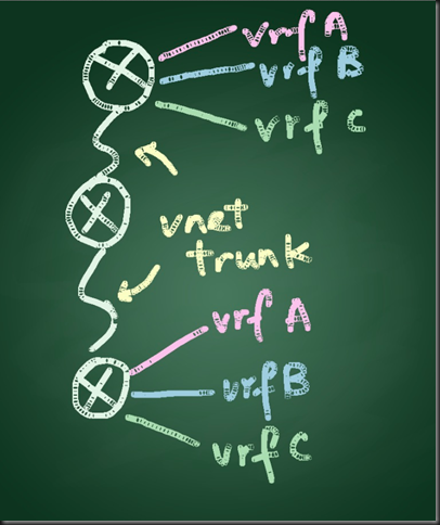
Scenario: In this scenario there are 3 routers interconnected, with 3 VRFs namely Android, IOS and WP7 created.  VNET trunk is configured in order to reduce the complexity and administration effort in configuring the routers in between.

Reference:  http://www.cisco.com/en/US/docs/ios/ios_xe/evn/configuration/guide/evn_confg_xe.html#wp1060221

Topology

VRF android (eth1/0), iOS (eth1/1) and wp7 (eth1/2) -- R4 (eth1/3 vnet trunk) -- (eth1/3 vnet trunk) R5 (eth1/0 vnet trunk) -- (eth1/3 vnet trunk) R6 -- VRF android (eth1/0), iOS (eth1/1) and wp7 (eth1/2)  
Image(14)

R4 Config

Current configuration : 2285 bytes

!

! Last configuration change at 01:38:17 HKT Sat Mar 24 2012

!

version 15.2

service timestamps debug datetime msec

service timestamps log datetime msec

!

hostname R4

!

boot-start-marker

boot-end-marker

!

!

vrf definition android

vnet tag 1001

!

address-family ipv4

exit-address-family

!

vrf definition ios

vnet tag 1002

!      

address-family ipv4

exit-address-family

!

vrf definition wp7

vnet tag 1003

!

address-family ipv4

exit-address-family

!

!

no aaa new-model

!

!

!

clock timezone HKT 8 0

ip cef

!

!

!

!

!

!

no ipv6 cef

!

!

multilink bundle-name authenticated

!

!

!

!

!

!

!

!

!

!

!

!

!

interface Ethernet0/0

no ip address

shutdown

!

interface Ethernet0/1

no ip address

shutdown

!

interface Ethernet0/2

no ip address

shutdown

!

interface Ethernet0/3

no ip address

shutdown

!

interface Ethernet1/0

 vrf forwarding android

ip address 10.1.1.1 255.255.255.0

!

interface Ethernet1/1

 vrf forwarding ios

ip address 10.2.2.1 255.255.255.0

!

interface Ethernet1/2

 vrf forwarding wp7

ip address 10.3.3.1 255.255.255.0

!

interface Ethernet1/3

 vnet trunk

ip address 192.168.1.1 255.255.255.0

 ip ospf vnet area 0

vnet name android

  ip ospf 2 area 0

!

vnet name ios

  ip ospf 3 area 0

!

vnet name wp7

  ip ospf 4 area 0

!

!

interface Serial2/0

no ip address

shutdown

serial restart-delay 0

!

interface Serial2/1

no ip address

shutdown

serial restart-delay 0

!

interface Serial2/2

no ip address

shutdown

serial restart-delay 0

!

interface Serial2/3

no ip address

shutdown

serial restart-delay 0

!

interface Serial3/0

no ip address

shutdown

serial restart-delay 0

!

interface Serial3/1

no ip address

shutdown

serial restart-delay 0

!

interface Serial3/2

no ip address

shutdown

serial restart-delay 0

!

interface Serial3/3

no ip address

shutdown

serial restart-delay 0

!

router ospf 2 vrf android

router-id 1.1.1.2

network 0.0.0.0 255.255.255.255 area 0

!

router ospf 3 vrf ios

router-id 1.1.1.3

network 0.0.0.0 255.255.255.255 area 0

!

router ospf 4 vrf wp7

router-id 1.1.1.4

network 0.0.0.0 255.255.255.255 area 0

!

router ospf 1

router-id 1.1.1.1

network 0.0.0.0 255.255.255.255 area 0

!

ip forward-protocol nd

!

!

no ip http server

!

!

!

!

control-plane

!

!

line con 0

logging synchronous

line aux 0

line vty 0 4

login

!

!

end

R5 Config

Building configuration...

Current configuration : 2290 bytes

!

version 15.2

service timestamps debug datetime msec

service timestamps log datetime msec

!

hostname R5

!

boot-start-marker

boot-end-marker

!

!

vrf definition android

vnet tag 1001

!

address-family ipv4

exit-address-family

!

vrf definition ios

vnet tag 1002

!

address-family ipv4

exit-address-family

!

vrf definition wp7

vnet tag 1003

!

address-family ipv4

exit-address-family

!

!

no aaa new-model

!

!

!

clock timezone HKT 8 0

ip cef

!

!

!

!

!

!

no ipv6 cef

!

!        

multilink bundle-name authenticated

!

!

!

!

!

!

!

!

!

!

!

!

!

interface Ethernet0/0

no ip address

shutdown

!

interface Ethernet0/1

no ip address

shutdown

!

interface Ethernet0/2

no ip address

shutdown

!

interface Ethernet0/3

no ip address

shutdown

!

interface Ethernet1/0

 vnet trunk

ip address 192.168.2.1 255.255.255.0

ip ospf vnet area 0

vnet name android

  ip ospf 2 area 0

!

vnet name ios

  ip ospf 3 area 0

!

vnet name wp7

  ip ospf 4 area 0

!

!

interface Ethernet1/1

no ip address

shutdown

!

interface Ethernet1/2

no ip address

shutdown

!

interface Ethernet1/3

vnet trunk

ip address 192.168.1.2 255.255.255.0

 ip ospf vnet area 0

vnet name android

  ip ospf 2 area 0

!

vnet name ios

  ip ospf 3 area 0

!

vnet name wp7

  ip ospf 4 area 0

!

!

interface Serial2/0

no ip address

shutdown

serial restart-delay 0

!

interface Serial2/1

no ip address

shutdown

serial restart-delay 0

!

interface Serial2/2

no ip address

shutdown

serial restart-delay 0

!

interface Serial2/3

no ip address

shutdown

serial restart-delay 0

!

interface Serial3/0

no ip address

shutdown

serial restart-delay 0

!

interface Serial3/1

no ip address

shutdown

serial restart-delay 0

!

interface Serial3/2

no ip address

shutdown

serial restart-delay 0

!

interface Serial3/3

no ip address

shutdown

serial restart-delay 0

!

router ospf 2 vrf android

router-id 2.2.2.2

network 0.0.0.0 255.255.255.255 area 0

!

router ospf 3 vrf ios

router-id 2.2.2.3

network 0.0.0.0 255.255.255.255 area 0

!

router ospf 4 vrf wp7

router-id 2.2.2.4

network 0.0.0.0 255.255.255.255 area 0

!

router ospf 1

router-id 2.2.2.1

network 0.0.0.0 255.255.255.255 area 0

!

ip forward-protocol nd

!

!

no ip http server

!

!

!

!

control-plane

!

!

line con 0

logging synchronous

line aux 0

line vty 0 4

login   

!

!

end

R6 Config

Building configuration...

Current configuration : 2285 bytes

!

! Last configuration change at 01:39:03 HKT Sat Mar 24 2012

!

version 15.2

service timestamps debug datetime msec

service timestamps log datetime msec

!

hostname R6

!

boot-start-marker

boot-end-marker

!

!

vrf definition android

vnet tag 1001

!

address-family ipv4

exit-address-family

!

vrf definition ios

vnet tag 1002

!      

address-family ipv4

exit-address-family

!

vrf definition wp7

vnet tag 1003

!

address-family ipv4

exit-address-family

!

!

no aaa new-model

!

!

!

clock timezone HKT 8 0

ip cef

!

!

!

!

!

!

no ipv6 cef

!

!

multilink bundle-name authenticated

!

!

!

!

!

!

!

!

!

!

!

!

!

interface Ethernet0/0

no ip address

shutdown

!

interface Ethernet0/1

no ip address

shutdown

!

interface Ethernet0/2

no ip address

shutdown

!

interface Ethernet0/3

no ip address

shutdown

!

interface Ethernet1/0

vrf forwarding android

ip address 10.4.4.1 255.255.255.0

!

interface Ethernet1/1

 vrf forwarding ios

ip address 10.5.5.1 255.255.255.0

!

interface Ethernet1/2

 vrf forwarding wp7

ip address 10.6.6.1 255.255.255.0

!

interface Ethernet1/3

 vnet trunk

ip address 192.168.2.2 255.255.255.0

ip ospf vnet area 0

vnet name android

  ip ospf 2 area 0

!

vnet name ios

  ip ospf 3 area 0

!

vnet name wp7

  ip ospf 4 area 0

!

!

interface Serial2/0

no ip address

shutdown

serial restart-delay 0

!

interface Serial2/1

no ip address

shutdown

serial restart-delay 0

!

interface Serial2/2

no ip address

shutdown

serial restart-delay 0

!

interface Serial2/3

no ip address

shutdown

serial restart-delay 0

!

interface Serial3/0

no ip address

shutdown

serial restart-delay 0

!

interface Serial3/1

no ip address

shutdown

serial restart-delay 0

!

interface Serial3/2

no ip address

shutdown

serial restart-delay 0

!

interface Serial3/3

no ip address

shutdown

serial restart-delay 0

!

router ospf 2 vrf android

router-id 3.3.3.2

network 0.0.0.0 255.255.255.255 area 0

!

router ospf 3 vrf ios

router-id 3.3.3.3

network 0.0.0.0 255.255.255.255 area 0

!

router ospf 4 vrf wp7

router-id 3.3.3.4

network 0.0.0.0 255.255.255.255 area 0

!

router ospf 1

router-id 3.3.3.1

network 0.0.0.0 255.255.255.255 area 0

!

ip forward-protocol nd

!

!

no ip http server

!

!

!

!

control-plane

!

!

line con 0

logging synchronous

line aux 0

line vty 0 4

login

!

!

end

Show command

R5#sh ip ospf nei

Neighbor ID     Pri   State           Dead Time   Address         Interface

1.1.1.1           1   FULL/DR         00:00:33    192.168.1.1     Ethernet1/3

3.3.3.1           1   FULL/BDR        00:00:37    192.168.2.2     Ethernet1/0

1.1.1.4           1   FULL/DR         00:00:36    192.168.1.1     Ethernet1/3.1003

3.3.3.4           1   FULL/BDR        00:00:31    192.168.2.2     Ethernet1/0.1003

1.1.1.3           1   FULL/DR         00:00:38    192.168.1.1     Ethernet1/3.1002

3.3.3.3           1   FULL/BDR        00:00:31    192.168.2.2     Ethernet1/0.1002

1.1.1.2           1   FULL/DR         00:00:32    192.168.1.1     Ethernet1/3.1001

3.3.3.2           1   FULL/BDR        00:00:30    192.168.2.2     Ethernet1/0.1001

R5#sh ip int brie

Interface              IP-Address      OK? Method Status                Protocol

Ethernet0/0            unassigned      YES NVRAM  administratively down down   

Ethernet0/1            unassigned      YES NVRAM  administratively down down   

Ethernet0/2            unassigned      YES NVRAM  administratively down down   

Ethernet0/3            unassigned      YES NVRAM  administratively down down   

Ethernet1/0            192.168.2.1     YES NVRAM  up                    up     

Ethernet1/0.1001       192.168.2.1     YES NVRAM  up                    up    

Ethernet1/0.1002       192.168.2.1     YES NVRAM  up                    up    

Ethernet1/0.1003       192.168.2.1     YES NVRAM  up                    up    

Ethernet1/1            unassigned      YES NVRAM  administratively down down   

Ethernet1/2            unassigned      YES NVRAM  administratively down down   

Ethernet1/3            192.168.1.2     YES NVRAM  up                    up     

Ethernet1/3.1001       192.168.1.2     YES NVRAM  up                    up    

Ethernet1/3.1002       192.168.1.2     YES NVRAM  up                    up    

Ethernet1/3.1003       192.168.1.2     YES NVRAM  up                    up     

Serial2/0              unassigned      YES NVRAM  administratively down down   

Serial2/1              unassigned      YES NVRAM  administratively down down   

Serial2/2              unassigned      YES NVRAM  administratively down down   

Serial2/3              unassigned      YES NVRAM  administratively down down   

Serial3/0              unassigned      YES NVRAM  administratively down down   

Serial3/1              unassigned      YES NVRAM  administratively down down   

Serial3/2              unassigned      YES NVRAM  administratively down down   

Serial3/3              unassigned      YES NVRAM  administratively down down    

R5#sh ip route vrf android

Routing Table: android

Codes: L - local, C - connected, S - static, R - RIP, M - mobile, B - BGP

       D - EIGRP, EX - EIGRP external, O - OSPF, IA - OSPF inter area

       N1 - OSPF NSSA external type 1, N2 - OSPF NSSA external type 2

       E1 - OSPF external type 1, E2 - OSPF external type 2

       i - IS-IS, su - IS-IS summary, L1 - IS-IS level-1, L2 - IS-IS level-2

       ia - IS-IS inter area, * - candidate default, U - per-user static route

       o - ODR, P - periodic downloaded static route, H - NHRP, l - LISP

       + - replicated route, % - next hop override

Gateway of last resort is not set

      10.0.0.0/24 is subnetted, 2 subnets

O        10.1.1.0 [110/20] via 192.168.1.1, 00:08:53, Ethernet1/3.1001

O        10.4.4.0 [110/20] via 192.168.2.2, 00:08:24, Ethernet1/0.1001

      192.168.1.0/24 is variably subnetted, 2 subnets, 2 masks

C        192.168.1.0/24 is directly connected, Ethernet1/3.1001

L        192.168.1.2/32 is directly connected, Ethernet1/3.1001

      192.168.2.0/24 is variably subnetted, 2 subnets, 2 masks

C        192.168.2.0/24 is directly connected, Ethernet1/0.1001

L        192.168.2.1/32 is directly connected, Ethernet1/0.1001

R5#show derived-config int eth1/3.1001

Building configuration...

Derived configuration : 183 bytes

!

interface Ethernet1/3.1001

description Subinterface for VNET android

encapsulation dot1Q 1001

vrf forwarding android

ip address 192.168.1.2 255.255.255.0

ip ospf 2 area 0

end

Sunday, February 26, 2012

Difference between "set dscp" and "set ip dscp" under policy-map

They are more or less the same in the IPv4 world.  The only difference is, set dscp will work for IPv4 and IPv6 and set ip dscp is for IPv4 only.


pandasw02(config-pmap-c)#set ?
  dscp        Set DSCP in IP(v4) and IPv6 packets
  ip          Set IP specific values
  precedence  Set precedence in IP(v4) and IPv6 packets


pandasw02(config-pmap-c)#set ip ?
  dscp        Set IP DSCP (DiffServ CodePoint)
  precedence  Set IP precedence

Wednesday, February 15, 2012

ASR 1000 OTV supports on IOS XE 3.5

Recently OTV is introduced to the ASR 1000 platform and is supported starting from IOS XE 3.5.  Basically the OTV support on ASR1K and N7K is similar, there are only a few difference that needs to note in this release:

- Support OTV with GETVPN on ASR1K
- No Adjacency server support, multicast WAN is required
- Support fragmentation
- Support of one Joint interface and one access interface per box

Friday, February 3, 2012

Save energy with Energywise

I am using a 3560-8PC PoE switch in my home lab and in order to save my electric bill, energywise has been implemented on the switchport in order to turn off the PoE power in the hours that I don't need it.

Example:  To turn on the PoE power every morning at 8am and turn off at 10pm.

interface FastEthernet0/7

 energywise level 10 recurrence importance 100 at 0 8 * * *
 energywise level 0 recurrence importance 100 at 0 22 * * *

Also I have written a web page to override this behavior, by triggering the expect script on my Linux box, details can be referred by this old post:
http://pandaeatsbamboo.blogspot.com/2009/12/script-to-turn-off-poe-power-using.html


Thursday, November 3, 2011

My LISP notes to share


What is LISP?
  • enables separation of IP addresses into two new numbering spaces: Endpoint Identifiers (EIDs) and Routing Locators (RLOCs)
  • Locator / Identifier Separation Protocol
Routing Locators (RLOCs)
  • topologically assigned to network attachment points, used for routing and forwarding of packets through the network
Endpoint Identifiers (EIDs)
  • assigned independently from the network topology, are used for numbering devices, aggregated along administrative boundaries
LISP then defines functions for mapping between the two numbering spaces and for encapsulating traffic originated by devices using non-routeable EIDs for transport across a network infrastructure that routes and forwards using RLOCs. Both RLOCs and EIDs are syntactically-identical to IP addresses; it is the semantics of how they are used that differs.

Definition
Provider Independent (PI) address
- An address block assigned from a pool where blocks are not associated with any particular location in the network
- Not topologically aggregatable in the routing system

Provider Assigned (PA) address
- An address block assigned to a site by each service provider to which a site connects
- Each block is sub-block of a service provider CIDR block and is aggregated into the larger block before being advertised into the global Internet

Routing Locator (RLOC)
- RLOC is an IPv4 or IPv6 address of an egress tunnel router (ETR)
- RLOC is the output of a EID to RLOC mapping lookup
- 1 EID maps to 1 or more RLOCs
- Multiple RLOCs can be assigned to the same ETR device or to multiple ETR devices at a site

Endpoint ID (EID)
- A 32-bit (IPv4) or 128-bit (IPv6) value used in the source and destination address fields of the first (most inner) LISP header of a packet
- The host obtains the destination EID similar to DNS
- Source EID is obtained via existing mechanisms used to set a host's local IP address
- An EID is allocated to a host from an EID-prefix block associated with the site where the host is located
- EIDs MUST NOT be used as LISP RLOCs

EID-prefix
- A power of two block of EIDs
- allocated to a site by an address allocation authority
- EID prefixes are associated with a set of RLOC address which make up a database mapping

Ingress Tunnel Router (ITR)
- A router which accepts an IP packet with a single IP header (does not contain a LISP header)
- The router treats this inner IP destination address as an EID and performs an EID to RLOC mapping lookup
- The router then prepends an outer IP header with one of its globally routable RLOCs in the source address field
- ITR receives IP packets from site end systems on one side and sends LISP-encapsulated IP packets toward the Internet on the other side

Egress Tunnel Router (ETR)
- An ETR is a router that accepts an IP packet where the destination address in the outer IP header is one of its own RLOCs
- The router strips the outer header and forwards the packet based on the next IP header found
- ETR receives LISP encapsulated IP packets from the Internet on one side and sends decapsulated IP packets to site end system on the other side

xTR
- ITR or ETR - tunnel endpoint

EID-to-RLOC cache
- short lived, on demand table in an ITR

EID to RLOC database
- global distributed database that contains all known EID-prefix to RLOC mappings

Basic Overview
- For routers between source host and ITR - destination address = EID
- For routers between destination host and ETR - destination address = EID
- For routers between ITR and ETR - destination address is RLOC
- IP addresses of the end systems = Endpoint Identifiers (EIDs)
- The IP address in the outer header are RLOCs
- ITR prepends a new LISP header to each packet and an egress tunnel router strips the new header
- ITR performs EID-to-RLOC lookups to determine the routing path to the ETR, which has the RLOC as one of its IP address

Basic Rules
- End systems only send to addresses which are EIDs. They don't know address are EIDs versus RLOCs but assume packets get to LISP routers and deliver packets to destination end system
- EIDs are always IP address assigned to hosts
- LISP routers mostly deal with RLOCs
- RLOCs are always IP addresses assigned to routers, preferably topological-oriented addresses from provider CIDR blocks
- EIDs are not expected to be usable for global end-to-end communication in the absence of an EID-to-RLOC mapping operation
- maximum 2 LISP headers can be prepended to a packet - first header as Location / Identity separation and second prepended header inside service provider for TE purposes
- Map-Requests can be sent on the underlying routing system topology or over an alternative topology
- Map-Replies are sent on the underlying routing system topology

Packet Flow
1. host1.example.abc.com wants to open a TCP connection to host2.example.xyz.com
2. It does a DNS lookup on host2.example.xyz.com
3. A/AAAA record is returned. This address is the destination EID
4. Locally assigned address of host1.example.abc.com is source EID
5. Packet is built and forwarded through the LISP site as a normal packet until reaches ITR
6. ITR must be able to map the EID destination to an RLOC of one of the ETRs at the destination site. The ITR will send a LISP Map-Request, and it should be rate-limited
7. When an alternate mapping system (ALT) is not in use, the Map-Request packet is routed through the underlying routing system. Otherwise the Map-Request packet is routed on an alternate logical topology
8. Map-requests arrives at one of the ETRs at the destination site
9. ETR looks at the destination EID of the Map-Request and matches it against the prefixes in the ETR's configured EID-to-RLOC mapping database. This is the list of EID-prefixes the ETR is supporting for site it resides in
10. If there is no match, Map-Request is dropped. Otherwise a LISP Map-Reply is returned to the ITR
11. The ITR receives the Map-Reply message, parses the messages and stores the mapping information from the packet. This information is stored in the ITR's EID-to-RLOC mapping cache. Note that the map cache is an on-demand cache
12. Subsequent packets from host1 to host 2 will have LISP header prepended by the ITR using the appropriate RLOC as the LISP header destination address learned from the ETR
13. ETR receives these packets directly, strips the LISP header and forwards the packets to the attached destination hosts

Tuesday, November 1, 2011

LISP 101 Pencast

I have spent a couple of days to study LISP, and I have summarized what I have learnt in the following pencast. Feel free to take a look and see if it helps you to have a basic understanding on how LISP works:

Cantonese version:
http://www.livescribe.com/cgi-bin/WebObjects/LDApp.woa/wa/MLSOverviewPage?sid=tgw6sG2FKbBn

English version:
http://www.livescribe.com/cgi-bin/WebObjects/LDApp.woa/wa/MLSOverviewPage?sid=GBrPsCc4H2bF

Saturday, January 1, 2011

Remote Access SSL VPN and DDNS setup

My environment:  IOS 15.1(3)T on ISR 892

I have been spending quite a lot of time on the road and it is much convenient if I have a way to remote access back to my home network.  In my home network I have setup the SSL VPN for remote access, as well as DDNS as I don’t have a fixed IP address for my home internet access.

1. You can register an account in dyndns.org to get your own DDNS entry

2.  Then you can configure DDNS update on the router, whenever there is an address change, it will update dyndns.org dynamically.

ip ddns update method DynDNS
HTTP
  add http://pandausername:pandapassword@members.dyndns.org/nic/update?system=dyndns&hostname=panda.dyndns.org&myip=<a>
  remove http://pandausername:pandapassword@members.dyndns.org/nic/update?system=dyndns&hostname=panda.dyndns.org&myip=<a>
interval maximum 1 0 0 0

3. Under your internet facing interface, configure the following command:

ip ddns update hostname panda.dyndns.org
ip ddns update DynDNS host members.dyndns.org

4. These are the webvpn configuration of my router, you can modify it for your own setup:

ip local pool vpn-pool 192.168.20.205 192.168.20.215

webvpn gateway panda.dyndns.org
ip address 1.2.3.4 port 443 
ssl trustpoint TP-self-signed-3650870944
logging enable
inservice
!
webvpn install svc flash:/webvpn/svc_1.pkg sequence 1
!
webvpn install svc flash:/webvpn/anyconnect-macosx-i386-2.3.2016-k9.pkg.zip sequence 2
!
webvpn context panda-context
ssl authenticate verify all
!
login-message "Welcome to Panda's home"
!
policy group panda-group
   functions svc-enabled
   banner "Login Successful"
   svc address-pool "vpn-pool"
   svc default-domain "panda.com"
   svc keep-client-installed
   svc rekey method new-tunnel
   svc split include 192.168.20.0 255.255.252.0
   svc dns-server primary 3.4.5.6
default-group-policy panda-group
gateway panda.dyndns.org
inservice

svc split is the split tunnel configuration that allows inserting a specific route to the client’s routing table.  svc split include means that only this route will be inserted to the host, other routes including default route will be based on the client’s own routing table.

5. Then you can use the AnyConnect client to remote access in full tunnel mode.

Sunday, July 18, 2010

EIGRP Stub Leak

EIGRP Stub Leak is a feature on Cisco router which allows EIGRP stub routers to leak route to peer routers.  This is achieved by leak-map, which is a route map that permit specific route to leak through.  A video is recorded to demonstrate how it works:

English version:

Chinese (Cantonese) version:

Friday, December 18, 2009

Auto Smartports Macros

My environment: Cisco 3560E, IOS 12.2(53)SE

Auto Smartports Macros is a feature that provide easy and automatic way in deploying switchport configuration based on the endpoint types.  The device is identified based on CDP, MAC address, OUI etc.

To enable Auto Smartports:

macro auto global processing

You might want to change the Auto Smarport Macro default value say for example the access and voice vlan, say for example if you want to change the IP phone access vlan to 10 and voice vlan to 20:

macro auto device phone ACCESS_VLAN=10 VOICE_VLAN=20

to verify the change, type:

show macro auto device


If the end device doesn’t support CDP, you can classify the device based on OUI (the first 3 bytes of the MAC address) or full MAC address.  Say for example you want to use mac address trigger for your digital media player (DMP) which is not defined in the default OUI list.

macro auto mac-address group DMP-MAC-GROUP

mac-address list 000f.1234.5678

macro auto execute DMP-MAC-GROUP built-in CISCO_DMP_AUTO_SMARTPORT ACCESS_VLAN=10

to verify, type:

show macro auto address-group

To see which port applies what macros:

show macro auto interface

image

show run interface gi0/16

image

Thursday, November 12, 2009

Medianet Autoprovisioning Demo

The switch recognize the device via CDP or by other customized ways to autoprovision the switchport configuration based on what kinds of device plugged in.  This auto smartport is available on 12.2(52)SE for most of the Cisco fixed configuration switches.

Friday, August 14, 2009

802.1q configuration on Linux

My environment: RH FC8 x86_64

1. Make sure the 802.1q module is added to the kernel 

modprobe 8021q

2. Add a subinterface.  In this example 170 is the 802.1q VLAN ID.

vconfig add eth0 170

3. Create the NIC configuration file

/etc/sysconfig/network-scripts/ifcfg-eth0.170

DEVICE=eth0.170
BOOTPROTO=none
IPADDR=192.168.170.1
NETMASK=255.255.255.0

4. Restart the network service

/etc/init.d/network restart

Tuesday, August 4, 2009

Enable IPv6 function on 3560/3750

You’ll need the proper SDM template to enable v4, v6 dual stack on 3560/3750/3560E/3750E

Switch(config) # sdm prefer dual-ipv4-and-ipv6 default

IPv6 General Prefix

My environment: Cisco Catalyst 3560E

IOS: 12.2(50)SE2, Advanced IP services

This is a handy feature provides quick and easy way to deploy prefix changes

Example:

ipv6 general-prefix DEV C0:A8:A::/48

int fa0/1

ipv6 addr DEV ::1/48

Your IPv6 address of fa0/1 is equal to C0:A8:A::1/48