Thursday, November 20, 2014

ISR - High CPU with the process SNMP Engine

I have a Cisco 1841 router running in my lab, running code 15.0(1)M, experienced high CPU (9x% in most of the time) after I started to manage and monitor it via Prime Infrastructure 2.1.

When I do a "show process cpu | inc SNMP", it shows the SNMP engine is consuming 90 something percent CPU:


 309  2437791424     2302245     105531 92.36% 76.00% 74.82%   0 SNMP ENGINE    

And when I do a "show snmp stat oid", the mostly queried OID is ipNetToMediaEntry

time-stamp  #of times requested  OID
22:52:04 HKT Nov 20 2014 5261 ipNetToMediaEntry.1
22:52:04 HKT Nov 20 2014 5261 ipNetToMediaEntry.2
22:52:03 HKT Nov 20 2014 5261 ipNetToMediaEntry.4
22:52:03 HKT Nov 20 2014 5260 ipNetToMediaEntry.3
22:50:43 HKT Nov 20 2014 4100 sysUpTime
22:50:22 HKT Nov 20 2014 2 ciscoEnvMonMIBNotificationEnables.4
22:50:22 HKT Nov 20 2014 1 ciscoEnvMonMIBNotificationEnables.3
22:50:22 HKT Nov 20 2014 2 ciscoEnvMonMIBNotificationEnables.2

As a workaround, I have created a view to exclude ipNetToMediaEntry with the following commands:

DW-DESK-RT01(config)#snmp-server view cutdown iso included
DW-DESK-RT01(config)#snmp-server view cutdown ipNetToMediaEntry excluded
DW-DESK-RT01(config)#snmp-server community dshome view cutdown RW

And now it looks much better:
DW-DESK-RT01(config)#do sh proc cpu | inc SNMP
 156           0           6          0  0.00%  0.00%  0.00%   0 SNMP Timers      
 263           0           3          0  0.00%  0.00%  0.00%   0 EEM ED SNMP      
 264           0           2          0  0.00%  0.00%  0.00%   0 EEM ED SNMP Noti 
 267           0           3          0  0.00%  0.00%  0.00%   0 EEM ED SNMP Obje 
 307  1366776000     2507583        545  0.00%  0.00%  0.00%   0 IP SNMP          
 309  2887259424     2304177     105638  0.00% 47.55% 68.40%   0 SNMP ENGINE      
 310        4000           2       2000  0.00%  0.00%  0.00%   0 IP SNMPV6        
 311           0           1          0  0.00%  0.00%  0.00%   0 SNMP ConfCopyPro 
 312           0           2          0  0.00%  0.00%  0.00%   0 SNMP Traps  

Probably I need to upgrade my IOS code for this legacy old box....

Friday, October 24, 2014

My First, Simple Game in iOS app store

This is my new attempt, to develop my first game in iOS app store using Spritebuilder.  Feel free to try it out and comment!  


Is 2960 / 2960-X a layer 3 switch?

Maybe you will answer NO immediately.  That is my understanding before too!  However recently I've found out this is not the case!  I have my old 2960 PD 8-port compact switch, upgraded with 15.0(2)SE6 LAN Base image and make it "routable"!  All you need to do is, change the SDM template, using the command "sdm prefer lanbase-default" and reboot it.  After that you will be able to configure SVI with IP addresses, as well as configure static routes and default gateway on that switches.  I have tried 2960-X and it resulted the same.  Just need to make sure you are using the LAN Base version of IOS, not LAN Lite as LAN Lite doesn't have this capability.  

More info here:

Wednesday, August 13, 2014

CWMS 2.0 Step-by-Step Installation Guide

Here comes the CWMS 2.0 step-by-step installation guide I have screen captured in my lab.  Due to lab resource constraint I don't have IRP in my lab, this guide will cover admin node, media node installation as well as UCM integration in a step-by-step manner.

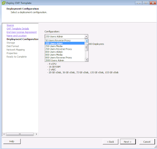
1. To install CWMS 2.0, you can first deploy the CWMS ova file via vCenter.  You can choose your desired sizing configuration.  In my case I have chosen 250 users configuration and firstly install the "Admin" node.  


2.  Enter the network configuration details for your CWMS Admin node.


3.  Once the OVA file is deployed, you can check the VM console via vCenter.


4.  Once the CWMS admin node deployment is completed, you can access the URL provided at the bottom of the screen to start the configuration wizard with a web browser.


5. Choose the language that you desired for your deployment.

6. In my case this is a newly deployed system.

7. Click Next.

8. Choose "Install a primary system"

9. Choose Automatic if you want to deploy the media virtual machine automatically by the admin node via vCenter.


10. Enter your vCenter information so that CWMS admin node can help you deploy media node and optionally IRP node.

11. Choose your host, datastore and VM port group.

12. Enter the FQDN of the media node that you are going to deployed.  I have already added the host record in my internal DNS server, so no IP address is needed to fill in.


13.  Optionally enable IRP if you want to allow external access to your CWMS.  In my case I will not install it for now.
14.  This is an additional IP address that is needed for WebEx site and admin access.  It must be on the same subnet as the admin node VM.

15.  Create DNS records for WebEx site and admin URL, forward map to the private VIP address.

16.  Click Next.

17.  The CWMS media node deployment will start.  Check your vCenter status.


18.  Check the deployment status on web deployment wizard and VM console.  Click Next.


19.  It will check the system against the hardware resources that you have.  In my lab I don't have enough CPU speed, but since it is a lab I will ignore it for now.

20.  Your admin node and media node is now ready.  Click Continue.

21. Configure your email server.


22.  Configure timezone and Locale.

23. Click Confirm.

24. Create admin account and create new password.

25.  Login with your new admin account.

26.  Congratulations!  You have basic setup completed.  Now let's work on the integration part.


27.  This is the CWMS system dashboard.  Click Users.

28. Choose Directory Integration.  Add CUCM server.  Provide UCM credentials.

29.  Click Enable LDAP Authentication if this is what you want.


30. You should now get all your users imported to CWMS!  Next thing we will work on the voice integration part.  Firstly put the system into maintenance mode.


31. Go to Settings > Audio.  Click Continue.

32.  Note the SIP configuration, click Continue.

33.  Add UCM address and ports information. 


34.  Click Continue.

35. Configure the dial-in number.  In my lab the number is 8567.


36.  Okay!  So basically the CWMS part is done.  Let's move to UCM.  Create 2 SIP Trunk Security profiles as below.


37.  Create 2 SIP trunks to CWMS load balancing and application point.  Reset trunk after create.


38.  Create Route pattern to route the call in number to CWMS via the Load Balance Point SIP trunk.


39.  Create SIP Route Pattern with IP address routing via the CWMS Application point SIP trunk. 


40.  Click Continue to turn off the system maintenance mode and the system will be automatically restart.


Done!  Try to make a call to your call in number and you can listen to the CWMS voice prompt!  Try to schedule / attend a meeting and see how it works!
Evernote helps you remember everything and get organized effortlessly. Download Evernote.